Skip to content

Unigrid: The National Park Service Publication System, Reconstructed

A reconstruction of selected National Park Service Unigrid relationships as executable constraints, with each claim identified as specified, derived, inferred, or adapted.

Abstract

Unigrid is the National Park Service publication system for informational folders. Development began in 1977. The system coordinates formats, grids, typography, maps, images, folds, paper, and printing conditions. Surviving brochures show the system in use; the 1985 design specification records many of the relationships used to make them.

Historical claims are classified as specified, derived, inferred, or adapted. This keeps what the historical record states or shows separate from what can be calculated, reconstructed, or introduced for contemporary use.

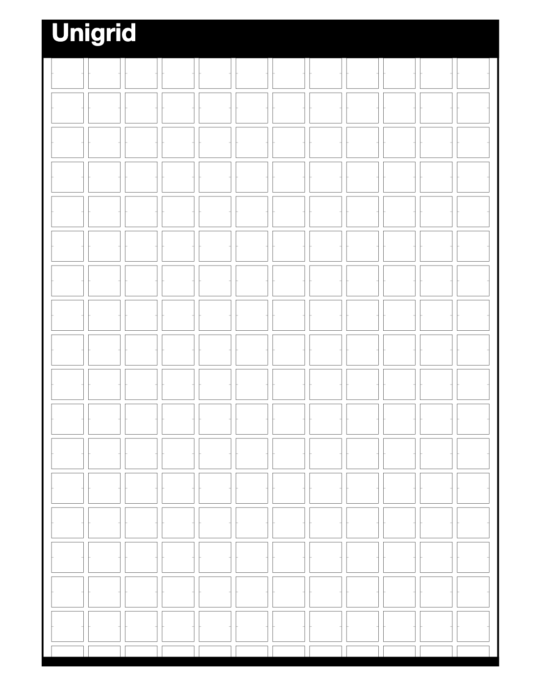
B6 is the principal geometric case. Its 420 × 594 millimetre sheet uses 84 × 80 point modules separated by 12 × 10 point intervals. The historical drawing establishes twelve complete columns by seventeen complete rows fully exposed beneath the title region. Together, the drawing, the specified 100-point title region, and the 90-point vertical pitch support the reconstruction of one complete row within the title region and a further row that begins before the lower trim and cannot be contained in full.

From there, the geometry becomes executable. Measurements become parameters, relationships become equations, and equations become constraints that software can generate and test. Fixed module dimensions, fixed intervals, integer coordinates and spans, a shared lattice, and material capacity form the transferable geometric model. Paper resolves that model within a finite sheet. A browser resolves it against available width and continuing document height while the selected module geometry remains fixed.

The reconstruction tests which relationships remain usable when the medium changes and keeps the limits of the historical evidence explicit.

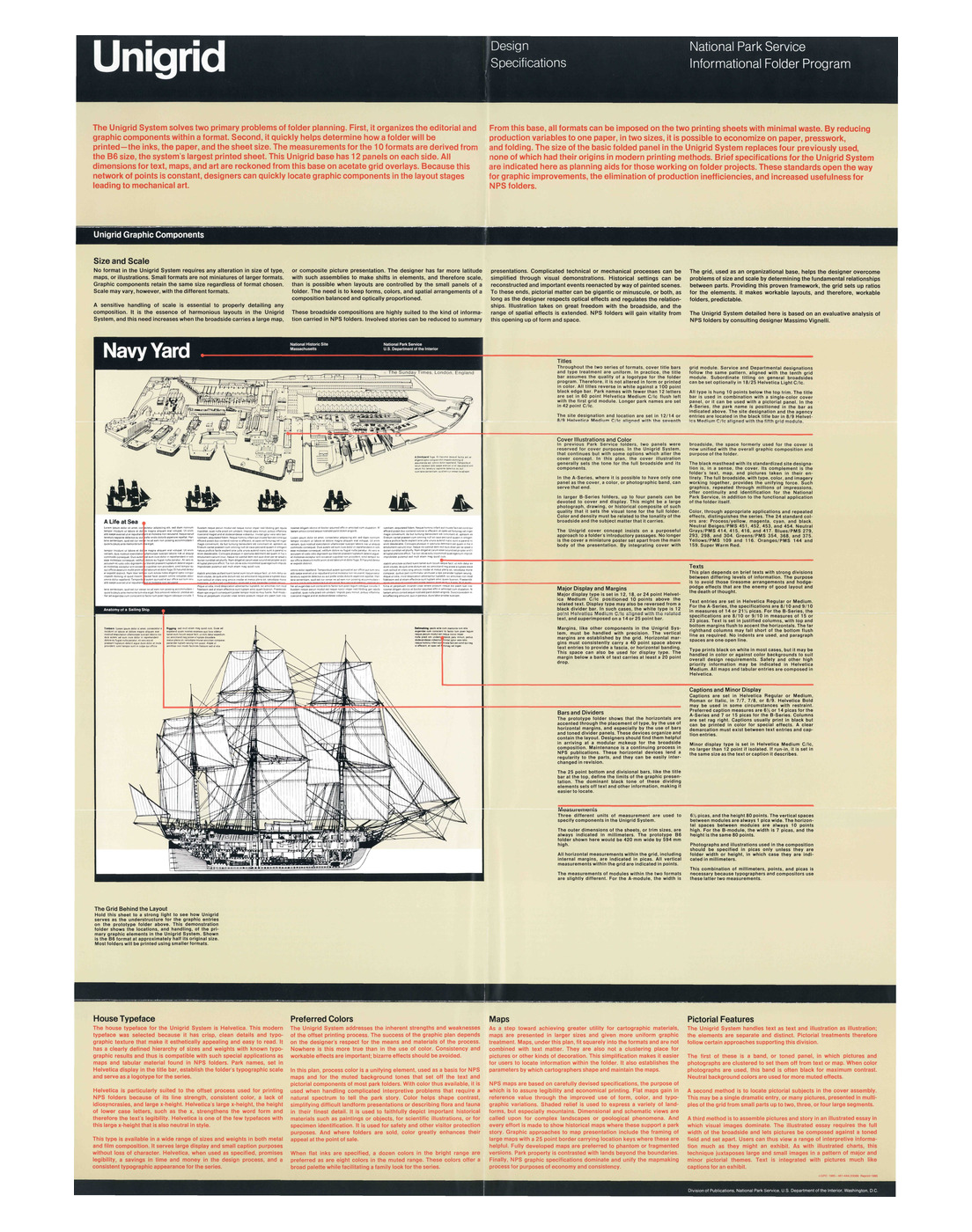
Figure 01Unigrid Design Specifications, National Park Service Informational Folder Program, 1985.
Page 1 of the National Park Service Unigrid Design Specifications, the primary source for the B-module geometry (7-pica by 80-point module, 1-pica by 10-point intervals) that Unigrid's default web geometry carries into CSS pixels.

Introduction

A surviving publication shows a design system in one finished state. A specification can preserve the dimensions, intervals, alignments, production rules, and permitted variations used to make many such states.

Surviving National Park Service folders show the system in use. They carry the black identification band, maps, photographs, historical illustrations, visitor information, and the folds that turned each broadside into something a visitor could carry. Each brochure records one arrangement. The specification records part of the structure that made many arrangements possible.

Which formal relationships define Unigrid? Which can the historical evidence establish? Which can be reconstructed or carried into another medium with their provenance still visible?

The study proceeds in two stages. Historical reconstruction recovers the documented relationships and derives further geometry from them, with B6 as the principal case. The second stage translates those relationships into computation and asks which still hold when the material changes from a fixed printed sheet to a variable browser field.

A historical measurement becomes a parameter; a relationship between parameters becomes an equation; the equation becomes a constraint that software can enforce. Permitted states can then be generated, invalid states rejected, and transformations tested against the relationships they carry forward.

B6 is the principal case because its trim, module dimensions, intervals, title region, lower bar, and published grid drawing can be read together. From that evidence, the reconstruction builds a reproducible geometric model with derived and contemporary claims identified separately.

What is the National Park Service Unigrid?

Unigrid is a system for making National Park Service informational folders. It coordinates graphic structure and physical production: the size and shape of the sheet, the grid within it, typography, maps and images, paper, printing, and the folds through which the broadside becomes an object a visitor can carry. The 1985 specification describes the grid as the pivotal component connecting work at the drafting table with work at the printing plant.1

Development began in 1977 under Publications Chief Vincent Gleason, with Massimo Vignelli engaged as consulting designer. Gleason sought a more efficient and economical approach to an expanding publications program. The first park brochure produced through Unigrid was issued for Clara Barton National Historic Site in 1978. In 1985, the program received a Presidential Design Award.2

The black title band became the system’s most immediately recognizable element. Its prominence can obscure the wider structure that made the program work. A Unigrid folder belongs to a fixed family of formats. It is laid out over a modular field. Type follows specified hierarchies and measures. Maps, images, bars, and text align through recurring relationships. Paper sizes, grain direction, press sheets, inks, and folds belong to the same production system.

Those conditions still allow substantial variation. One brochure may open around a large relief map. Another may give most of its broadside to an illustrated historical scene. Another may carry dense visitor information in short text banks. The National Park Service describes this flexibility directly: the grid establishes boundaries for individual elements while brochures of the same size and shape can still look very different.2

What makes the folders a family is the recurrence of those relationships across very different layouts.

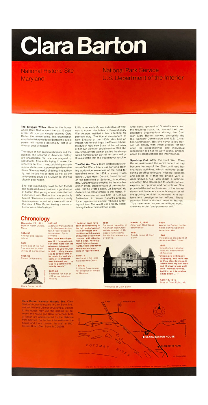
Figure 02Clara Barton National Historic Site, 1978, identified by the National Park Service as the first park brochure produced through Unigrid.
The 1978 Clara Barton National Historic Site folder: the park name set in white across a black title band at the head of the sheet, a red panel beneath it carrying the site and agency designations, three columns of text, a red Chronology band with a portrait of Barton and a photograph of the house at Glen Echo, and a red location map across the foot.

Historical context

Why the National Park Service needed Unigrid

National Park Service visitor publications long predate Unigrid. As the National Park System expanded, its folders accumulated many formats, fonts, and folding methods. As their number grew, the publications became harder to produce and maintain. In 1977 Gleason sought a more efficient and cost-effective approach.2

The 1985 specification states the problem exactly. It identifies two primary tasks in folder planning. The first is organizing editorial and graphic components within a format. The second is determining how the folder will be printed: inks, paper, and sheet size.1

Graphic order and production economy enter together. Format, paper, grid, fold, and type become known conditions before the particular park story is resolved. The designer can then give more attention to the specific publication: the territory a map requires, the sequence through which a history should unfold, the position of visitor information, or the relationship between an image and the text beside it.

Unigrid addressed institutional scale through standardization and left room for each publication to differ.

Vincent Gleason and the publications program

Vincent Gleason was Publications Chief when development of Unigrid began. National Park Service sources trace the program’s institutional beginning to Gleason: he sought a new publication system and engaged Vignelli’s expertise.2

Gleason had been thinking about the conditions of this work for years. In April 1964, as Chief of the Publications Branch, he proposed bringing publications, museum and exhibit work, audiovisual presentations, and motion pictures together in purpose-built facilities at Harpers Ferry. His proposal argued that closer contact among the creative branches would improve communication and produce more unified work for individual parks.3

That earlier proposal helps explain what Gleason was trying to solve: who worked together, where the work was made, which equipment and spaces supported it, and how different interpretive media could share a common purpose.

Vignelli’s recollection gives the other side of their meeting. In his 2011 oral history, he remembered giving a lecture in Washington with Gleason in the audience. Gleason approached him afterward and later came to New York to discuss the Park Service’s publication problems. Vignelli recalled that those discussions led to the system called Unigrid.4

Figure 03Vincent Gleason's 1964 proposal for the Harpers Ferry interpretive design center.
The sheets of Vincent Gleason’s April 1964 employee-suggestion form, fanned out and photographed: the handwritten heading Here’s MY idea, the typed suggestion that the National Park Service locate the creative functions of its Washington interpretive staff in a shop at Harpers Ferry, West Virginia, the continuation pages, and the signed suggestion acknowledgment.

Massimo Vignelli and the design of Unigrid

The 1985 specification identifies Massimo Vignelli as consulting designer and states that the system is based on his evaluative analysis of existing National Park Service folders.1

Vignelli’s oral history describes a program wider than a page grid. He recalled establishing a grid and format, a direction for information, rules for images, cartography, writing, folders, books, and other publications. He also described regular visits to Harpers Ferry and Washington as Park Service designers began working within the system.4

In his account, Unigrid is a language practiced by many people. Vignelli did not claim authorship of every brochure. He described a system used by Park Service designers to create continuity across the program and respond to individual assignments.

The Vignelli Center identifies members of the Park Service design team as Melissa Cronyn, Nicholas Kirillof, Dennis McLaughlin, Linda Meyers, Philip Musselwhite, Mitchell Zetlin, and Vincent Gleason, Chief of the Division of Publications. Later histories give Dennis McLaughlin a specific design credit on the 1977 system. Together, these records place Vignelli’s consulting role within a wider Park Service design team.56

Clara Barton National Historic Site, 1978

The National Park Service identifies the 1978 Clara Barton National Historic Site brochure as the first park brochure produced through Unigrid.2

The brochure is the first park-specific Unigrid publication. The black identification band, the relationship of title to field, the broad horizontal organization, and the integration of text and image can be read in an object made for a specific historic site rather than in the abstract language of a specification.

The timing matters too. Development began in 1977; by 1978 Unigrid had already left the drafting table and become something people could fold, carry, and use.

Research method

Evidence classes

This study uses four evidence classes.

Evidence classMeaning
SpecifiedA value or relationship stated or unambiguously depicted in the historical source.
DerivedA result calculated from identified evidence by a reproducible method.
InferredA reconstruction that depends on an assumption or interpretation the source does not fully establish.
AdaptedA decision introduced by KhannaOffice for contemporary use.

A derived value is only as sound as the evidence it starts from. Exact arithmetic establishes the consequence of a premise; it cannot strengthen that premise as historical evidence. A numerical conversion introduced for comparison is still a conversion. A browser rule is contemporary even when it closely preserves a historical relationship.

Primary sources and provenance

The principal technical source is the 1985 reprint of Unigrid Design Specifications: National Park Service Informational Folder Program, issued by the National Park Service Division of Publications. The two-sided sheet documents formats, grid dimensions, title treatment, typography, colour, maps, pictorial methods, broadside logic, paper, folding, and production.1

NPSHistory.com hosts the facsimile used here. It is an independent archive; the National Park Service document is the historical source. Citations name the issuing body, title, date, side, and internal section where possible.

The National Park Service’s Harpers Ferry Center history records the institutional chronology and the agency’s present account of Unigrid.2 Vincent Gleason’s 1964 proposal records his earlier approach to the institutional conditions of publication and interpretive media.3 Massimo Vignelli’s 2011 Smithsonian oral history gives his first-person account of meeting Gleason and developing the system.4 The Vignelli Center holds publication records and names members of the Park Service design team.5 Meggs’ History of Graphic Design provides a secondary attribution record for Vignelli, Gleason, and Dennis McLaughlin.6

UniDescription independently describes the boxes in the historical grid illustration as twelve wide and seventeen deep.7 It corroborates a count directly visible in the primary drawing.

These sources perform different work, and each is used only for what it can establish.

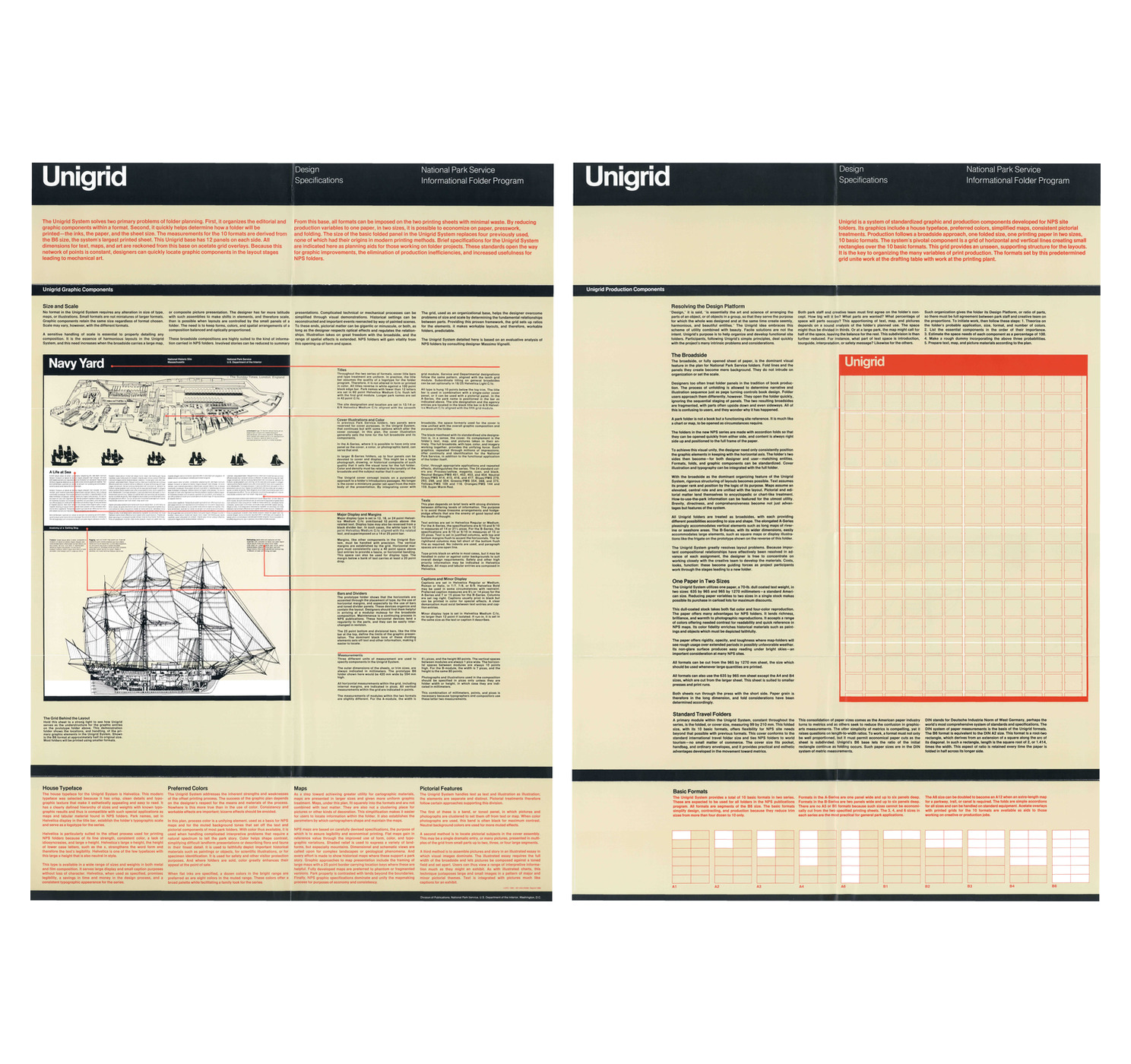
Figure 04Both sides of the 1985 specification, shown at a scale where the original evidence remains legible.
Both sides of the 1985 Unigrid Design Specifications placed side by side: page 1, Unigrid Graphic Components, with the Navy Yard prototype folder, at the left; page 2, Unigrid Production Components, with the B6 grid drawing and the ten basic formats, at the right.

Methodological context

The method draws on several neighbouring traditions: design history, generative design, cultural-heritage reconstruction, digital preservation, and software preservation. Several of these traditions treat designed artifacts as evidence of rules and document how reconstructions follow from their sources.

Simon treats designed systems as objects of systematic study, examined in relation to their purposes and environments.8 Stiny and Gips made the argument visual through shape grammars: classes of forms can be specified by generative rules rather than catalogued only as finished examples.9 This paper does not claim that Unigrid is a shape grammar in their formal sense. Their distinction allows finished artifacts to be studied as outcomes of a rule system.

The London Charter requires research sources to be identified and evaluated, uncertainty to be stated, and the analytical, deductive, interpretative, and creative decisions connecting sources to computational outcomes to be documented.1011 Hugh Denard describes this requirement as a problem of intellectual transparency: a digital reconstruction should allow a reader to understand the character and limits of the knowledge claim it makes.12 The four evidence classes used here apply that requirement to individual geometric relationships.

Digital-preservation research poses a related question: which properties must survive when an object changes technical environment? The InSPECT project developed methods for identifying “significant properties” whose preservation supports continued access, use, meaning, authenticity, and integrity across transformations.13 Christoph Becker has argued that such properties become meaningful within preservation systems and performances rather than existing as self-evident technical attributes.14 This reconstruction concentrates on relationships that can be established from the evidence and formalized for another medium. The larger historical system includes editorial judgment, cartography, image commissioning, print procurement, folding, and institutional practice.

Software introduces a further preservation layer. Di Cosmo and Zacchiroli argue for source code as a first-class preservation object because it contains human-readable technical knowledge and records the evolution of software systems.15 Here, source code and verification reports record the contemporary implementation. The historical specification records the evidence used to reconstruct selected relationships. The two records answer different questions, so the paper keeps them separate.

In this paper, executable preservation means encoding historical relationships so they can generate states, reject invalid ones, and be tested while their provenance remains visible. Here, the term applies only to the relationships encoded in the model.

The Unigrid system

The ten formats

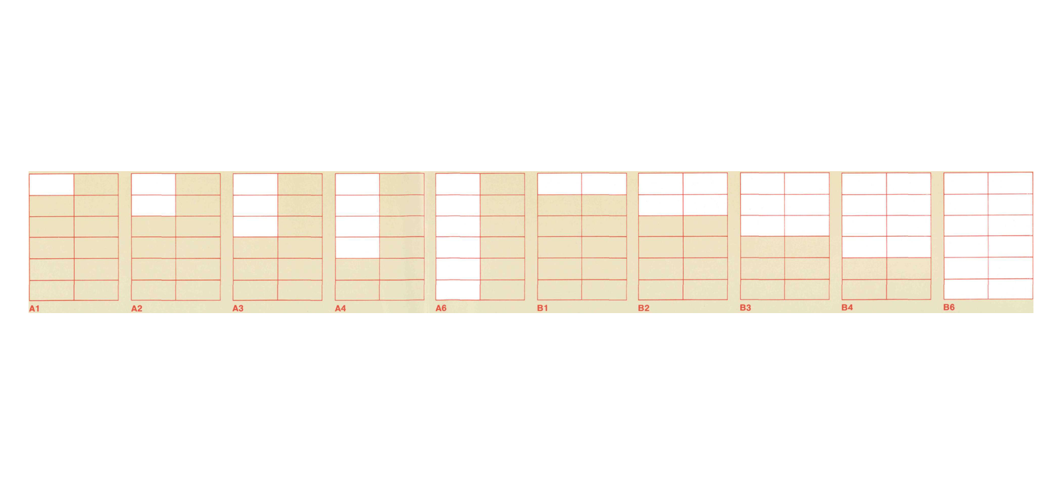
Unigrid provides ten basic formats in two series. A-Series formats are one folded panel wide. B-Series formats are two folded panels wide. Each series includes depths of one, two, three, four, and six panels. A5 and B5 are omitted because those sizes cannot be cut economically from the two specified printing sheets.16

The folded panel measures 99 × 210 millimetres. From that panel structure, the open formats are:

FormatOpen trimEvidence class
A1210 × 99 mmDerived
A2210 × 198 mmDerived
A3210 × 297 mmDerived
A4210 × 396 mmDerived
A6210 × 594 mmDerived
B1420 × 99 mmDerived
B2420 × 198 mmDerived
B3420 × 297 mmDerived
B4420 × 396 mmDerived
B6420 × 594 mmSpecified

A6 can be doubled to make A12 where an extra-length map is useful for a parkway, trail, canal, or another linear subject. The specification uses accordion folds for the format family.16

The name B6 belongs to the National Park Service’s internal format system. The specification states that its 420 × 594 millimetre B6 corresponds to DIN A2. It therefore differs from the much smaller paper size commonly called DIN or ISO B6.16 The family remains recognizable across very different publications.

Figure 05The ten basic Unigrid formats, A1–A6 and B1–B6.
The Basic Formats band from the foot of page 2 of the 1985 specification: ten ruled format diagrams in a row, labelled A1, A2, A3, A4, A6, B1, B2, B3, B4 and B6, each shown as a panel-and-fold subdivision of the B6 sheet.

The broadside as the organizing field

The fully opened sheet, or broadside, is the main field for layout. Fold lines and the panels they create remain part of the object, while the layout is organized across the larger sheet.17

A park folder is handled in motion. It is opened to find a map, turned to locate a piece of information, folded again, placed in a pocket, and opened later somewhere else. The specification responds by treating the folder more like a chart or map than a sequence of small book pages. Accordion folds allow either side to open quickly, and content remains oriented to the larger broadside.

Maps, photographs, drawings, titles, and text can therefore be arranged across the full sheet. The fold determines the physical object. The layout is organized at the scale of the broadside.

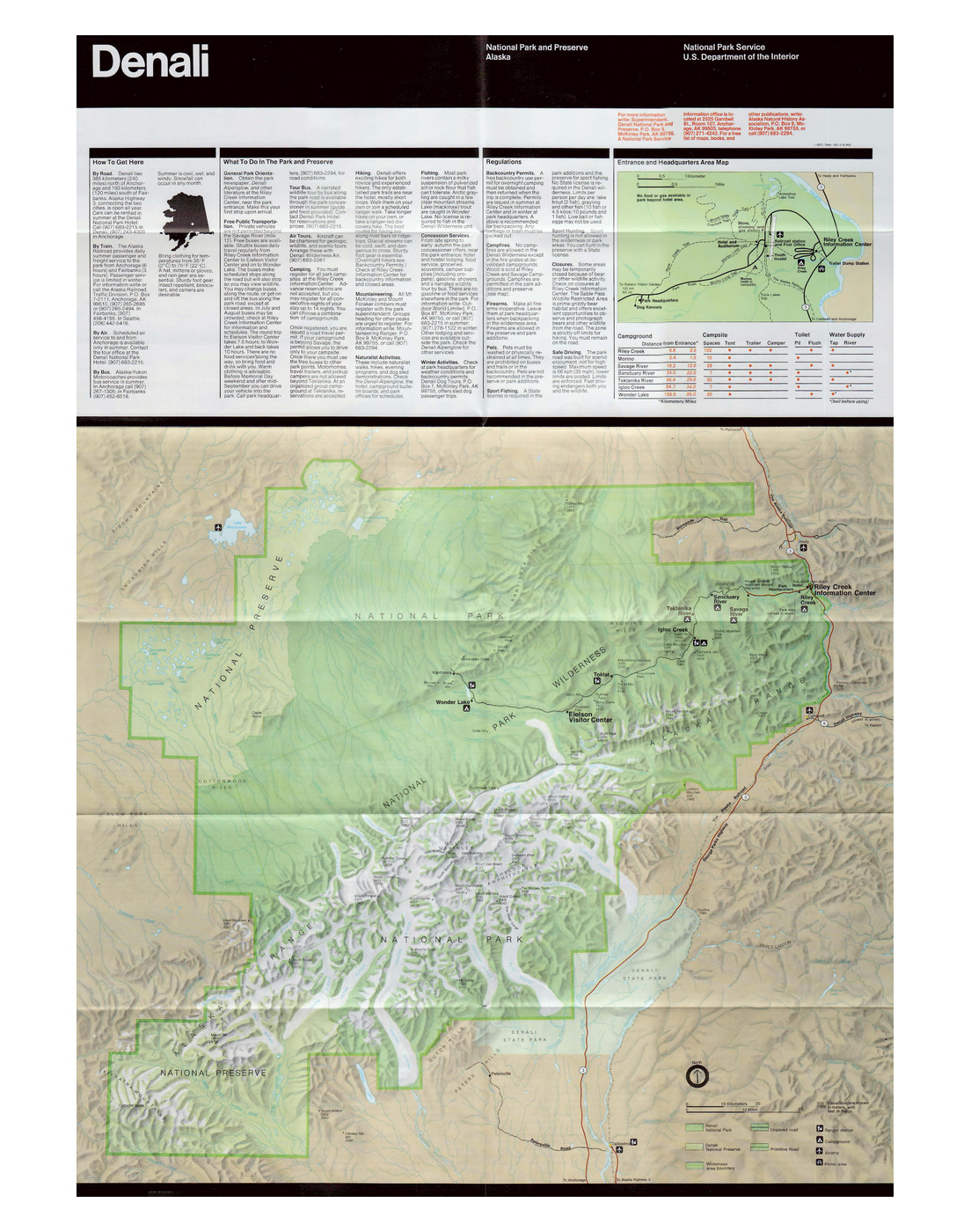
Figure 06Denali, back view, showing cartographic and pictorial material organized across the broadside.
The back side of the 1984 Denali National Park and Preserve folder, opened flat: the black Denali title band across the head, banks of visitor text and a green entrance-area inset map with a campground table below it, and the park’s full relief map filling the lower two thirds of the broadside, the park and preserve boundaries drawn in green over shaded terrain.

Grid and module

The grid is the common coordinate structure beneath the format family. The 1985 specification describes acetate overlays used to locate graphic components during layout and mechanical art. The grid remains constant as the formats change.18

The A- and B-Series use related modules. Both are 80 points high. The A-module is 6½ picas wide. The B-module is 7 picas wide. Spaces between module columns are one pica; spaces between module rows are 10 points. Since one pica equals 12 points, the B-module measures 84 × 80 points, separated by 12 × 10 point intervals.

Three units of measure appear in the specification. Trim sizes are stated in millimetres. Horizontal grid measurements are stated in picas. Vertical grid measurements are stated in points. The source explains that typographers and compositors work in the latter two units.19

The specification describes the grid as an unseen supporting structure. On the specification sheet itself, the reader is instructed to hold the paper to a strong light so the grid on one side can be seen beneath the prototype on the other. It is a wonderfully literal demonstration of the principle: the grid is present even when it disappears from view.

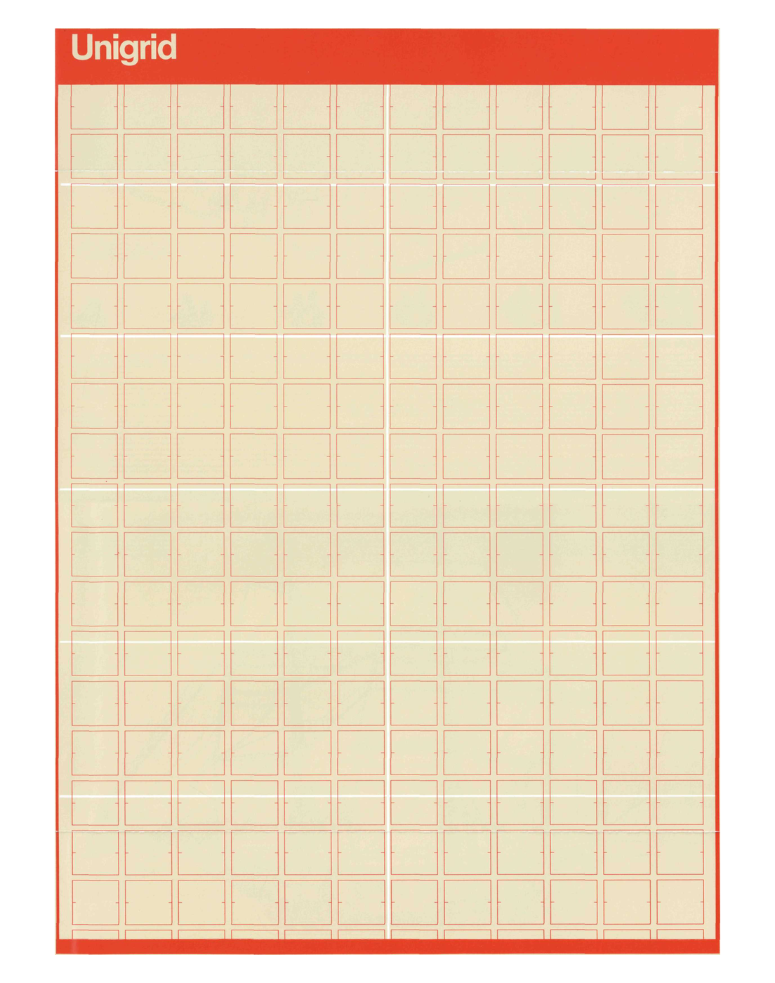
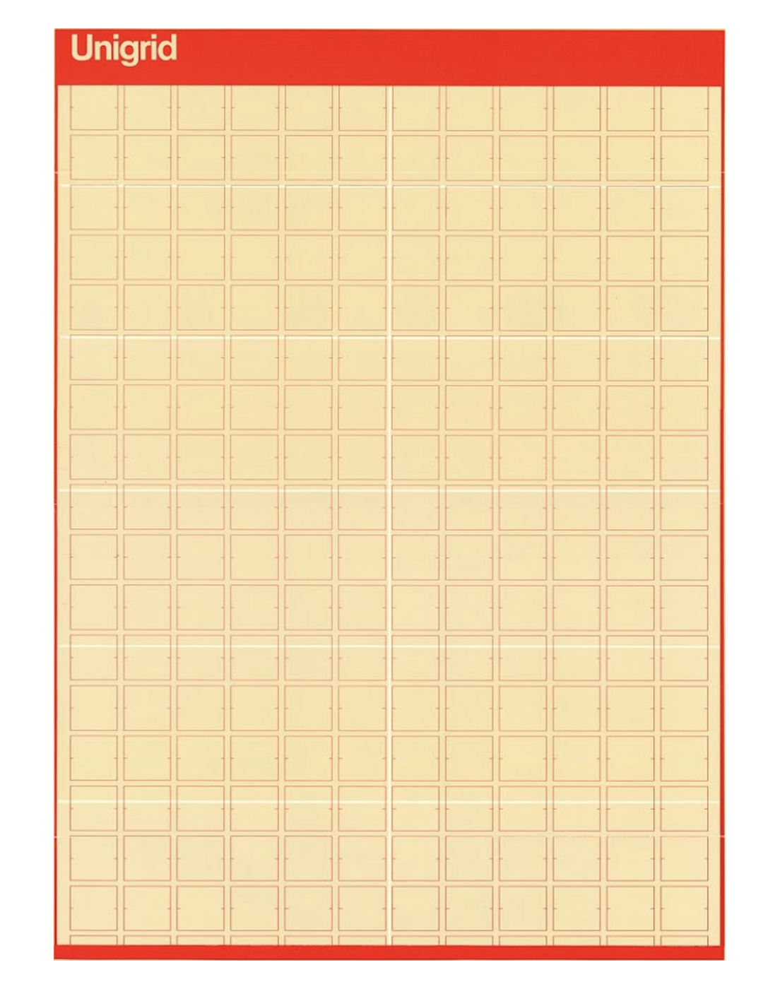
Figure 07The B6 grid drawing from the 1985 specification.
The B6 grid drawing from page 2 of the 1985 specification: a red frame carrying the Unigrid title bar above a lattice of small rectangles, twelve complete columns wide, each module drawn with its own corner ticks.

Typography

The 1985 specification names Helvetica as the house typeface for Unigrid. It specifies Helvetica for display type, body text, maps, tables, and captions, connecting the choice to offset printing, the available range of weights and sizes, and Helvetica’s large x-height.20

The title bar carries the most explicit hierarchy. Park names shorter than twelve letters are set in 60-point Helvetica Medium, aligned with the first grid module. Longer park names use 42 point. In the B-Series, the site designation and location are set in 12/14 or 8/9 Helvetica Medium and align with the seventh module. Service and Departmental designations align with the tenth. Title type hangs 10 points below the top trim.

B-Series body text uses 8/10 or 9/10 Helvetica Regular or Medium in measures of 15 or 23 picas. A-Series measures are 14 or 21½ picas. Text is justified. Text banks align at their upper and lower edges, while the far-right column may end short. Paragraphs carry no indent and are separated by one open line.

Major display type uses 12, 18, or 24 point Helvetica Medium and sits 10 points above its related text. Captions use Helvetica Regular or Medium, roman or italic, at 7/7, 7/8, or 8/9. Preferred B-Series caption measures are 7 or 15 picas.20

The National Park Service’s later historical account records Helvetica and Times Roman among the program’s original typefaces and Frutiger and NPS Rawlinson in later standards. The 1985 specification therefore documents one stage in a system that continued to develop.2

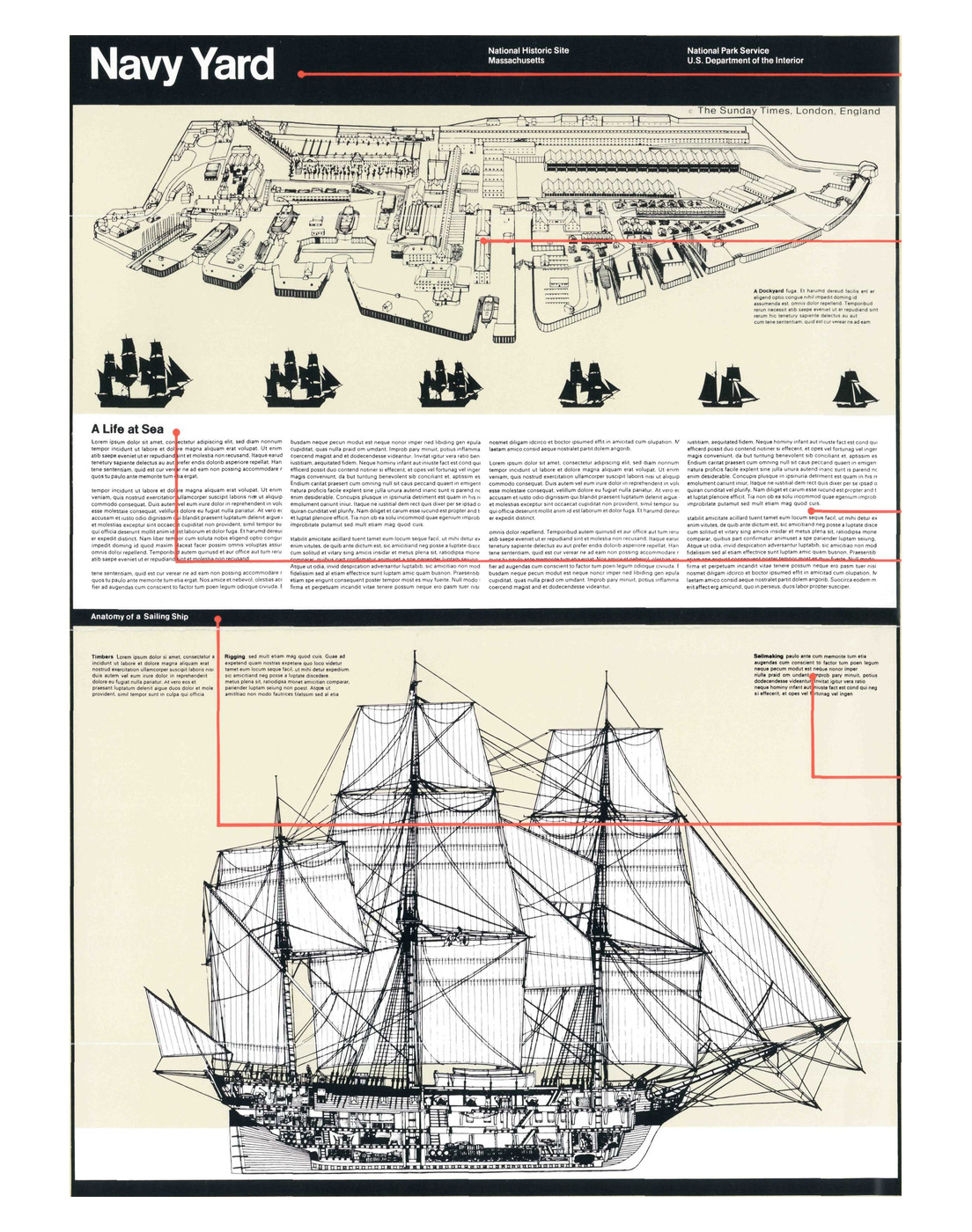
Figure 08The Navy Yard prototype and title alignment rules on page 1 of the specification.
The Navy Yard prototype folder on page 1 of the 1985 specification: the black title bar reading Navy Yard with its site and agency designations, an axonometric drawing of the yard, a rank of ship silhouettes, the A Life at Sea text block, and a rigged sailing ship below, with red rules ruled across the panel to show the horizontal alignments the title bar sets.

Titles, bars, and recurring horizontal relationships

Across both series, the cover title treatment is uniform. The title bar is 100 points high and black; titles reverse in white. The specification describes the bar as taking on the quality of a logotype for the folder program.21

Horizontal organization continues through bottom bars, divisional bars, margins, and fascia. Bottom and divisional bars are 25 points high. The specification connects their regularity to layout and maintenance: horizontal parts can be exchanged as publications are revised.

A 40-point horizontal space is maintained above text entries, and a bank of text carries at least a 20-point drop below. These relationships give the broadside a recurring horizontal rhythm that works with the module grid without requiring every element to fill a complete module.

Colour

The 1985 specification identifies 24 standard colours.

GroupColours
ProcessYellow, magenta, cyan, black
Neutral beigesPMS 451, 452, 453, 454
Neutral greysPMS 414, 415, 416, 417
BluesPMS 279, 293, 298, 304
GreensPMS 354, 368, 375
YellowsPMS 109, 116
OrangesPMS 144, 159
RedSuper Warm Red

The document also identifies twelve preferred bright flat inks and eight muted flat inks. Colour is used across maps, scientific and historical illustration, safety information, photographs, and background fields.22

The restricted palette gave the office a common production vocabulary and left considerable variation between brochures.

Figure 09Preferred Colors, page 1 of the 1985 specification.
The Preferred Colors column from the foot of page 1 of the 1985 specification, setting out the system's use of process color as a unifying element and its restriction to a dozen bright and eight muted inks.

Maps and pictorial material

The specification calls for larger maps with a more uniform graphic treatment. It keeps maps free of unrelated text and decorative image clusters so cartographic information can be found and maintained more directly. Large maps may carry a 25-point border containing location keys where useful.23

Images may sit within a toned band, join the cover assembly, or form an illustrated essay across the broadside. Images can occupy small areas or several large grid segments, depending on the hierarchy of the story.

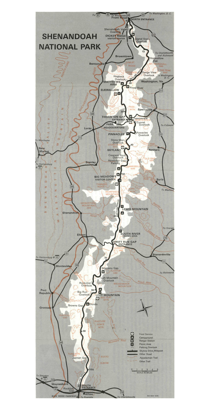
Figure 10aNational Park Service map example.
The park map panel from the back of the 1979 Shenandoah National Park folder: the long ridge of the park drawn in white against a grey surround, Skyline Drive running its length with mileposts, overlooks, visitor centres and campgrounds keyed along it, watercourses and trails in red, and a symbol key and scale bar set into the lower right of the panel.

Printing, paper, and folding

The production plan uses 70-pound dull-coated text stock in two press-sheet sizes: 635 × 965 millimetres and 965 × 1270 millimetres. The larger sheet accommodates all ten basic formats. The smaller accommodates every format except A4 and B4.24

Both sheets run through the press on the short side. Paper grain therefore lies in the long dimension, and the format and fold system is planned with that grain direction in mind.

Format family, paper stock, grid, press sheets, inks, and folds belong to one production method. A coordinate on the designer’s overlay is connected, through the system, to a physical sheet that will pass through a press and later through someone’s hands.

For this reconstruction, that connection matters: the grid ties graphic decisions to material consequences in production.

Figure 10bNational Park Service illustration example.
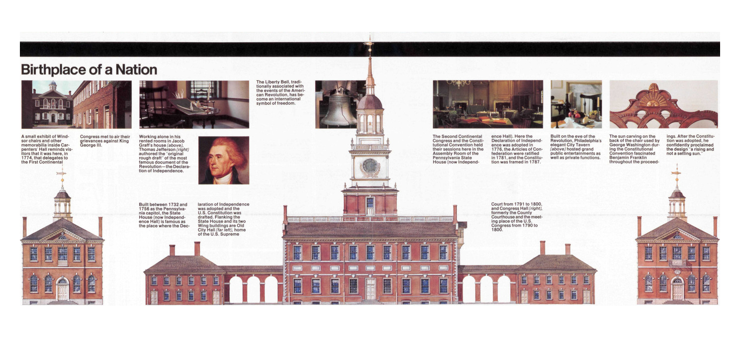
The band of painted architectural elevations from the back of the 1989 Independence National Historical Park folder: Congress Hall, the Pennsylvania State House with its wing buildings and clock tower, and Old City Hall, drawn to a common scale in a row across the broadside with short captions set between them.

Constraint and variation

Unigrid establishes recurring conditions before an individual folder is laid out. Format, module, title treatment, type hierarchy, paper, and production method are known in advance.

The specification calls this allocation of content the Design Platform. Park staff and the creative team determine the intended use of the folder, identify its essential components, estimate how much space each requires, make a rough dummy, and prepare text, maps, and images to that plan.25

A large park may give half of its broadside to a map. A historic site may organize its sheet around archival material or a reconstructed scene. A linear landscape may choose an elongated A-format. Each publication is made within the same system of formats, grids, typography, and production rules.

Vignelli later described Park Service designers working within a common language while producing hundreds of individual publications.4 That is the useful tension in Unigrid: the system decides a great deal before the designer begins, but it does not decide the publication for them.
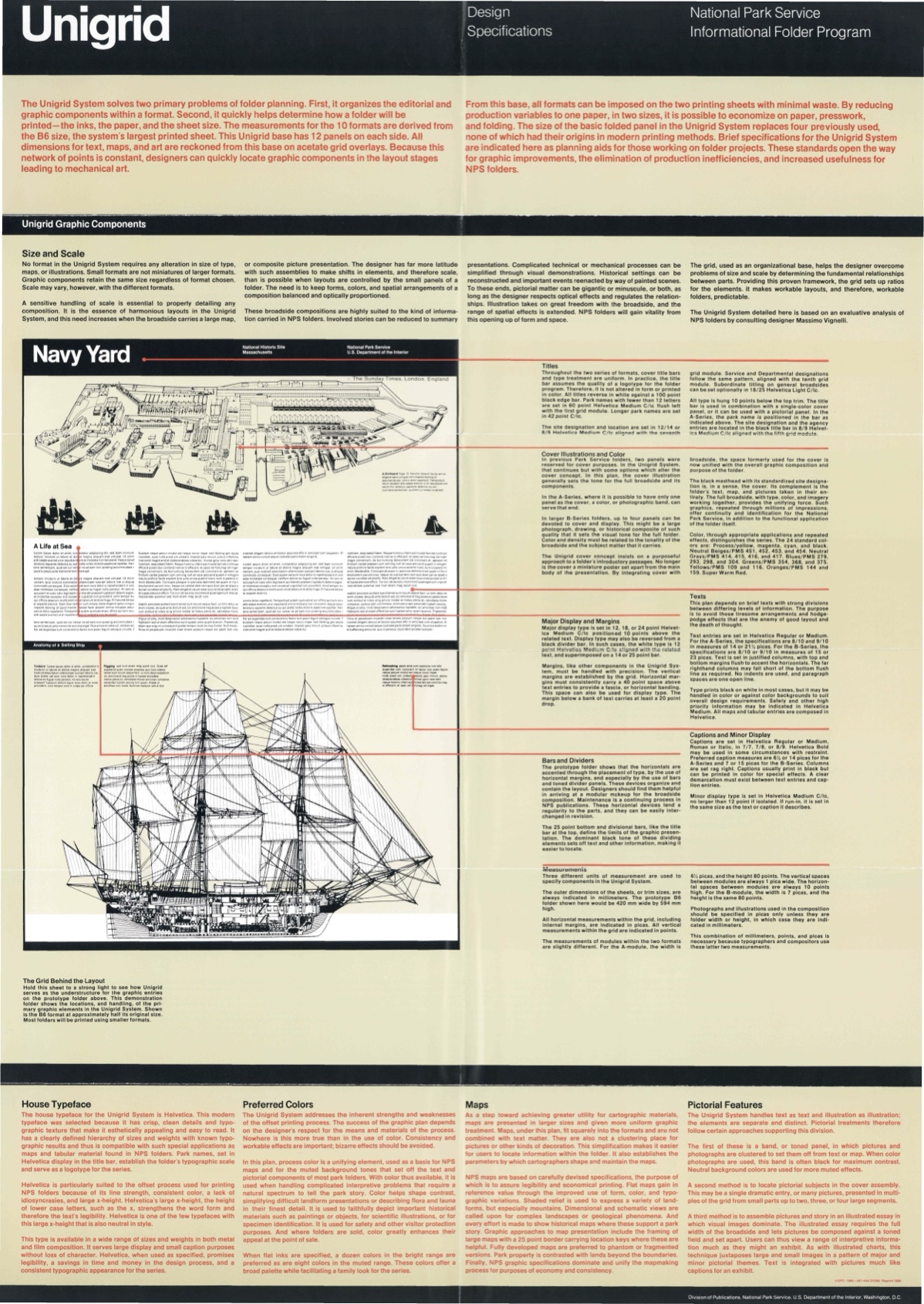
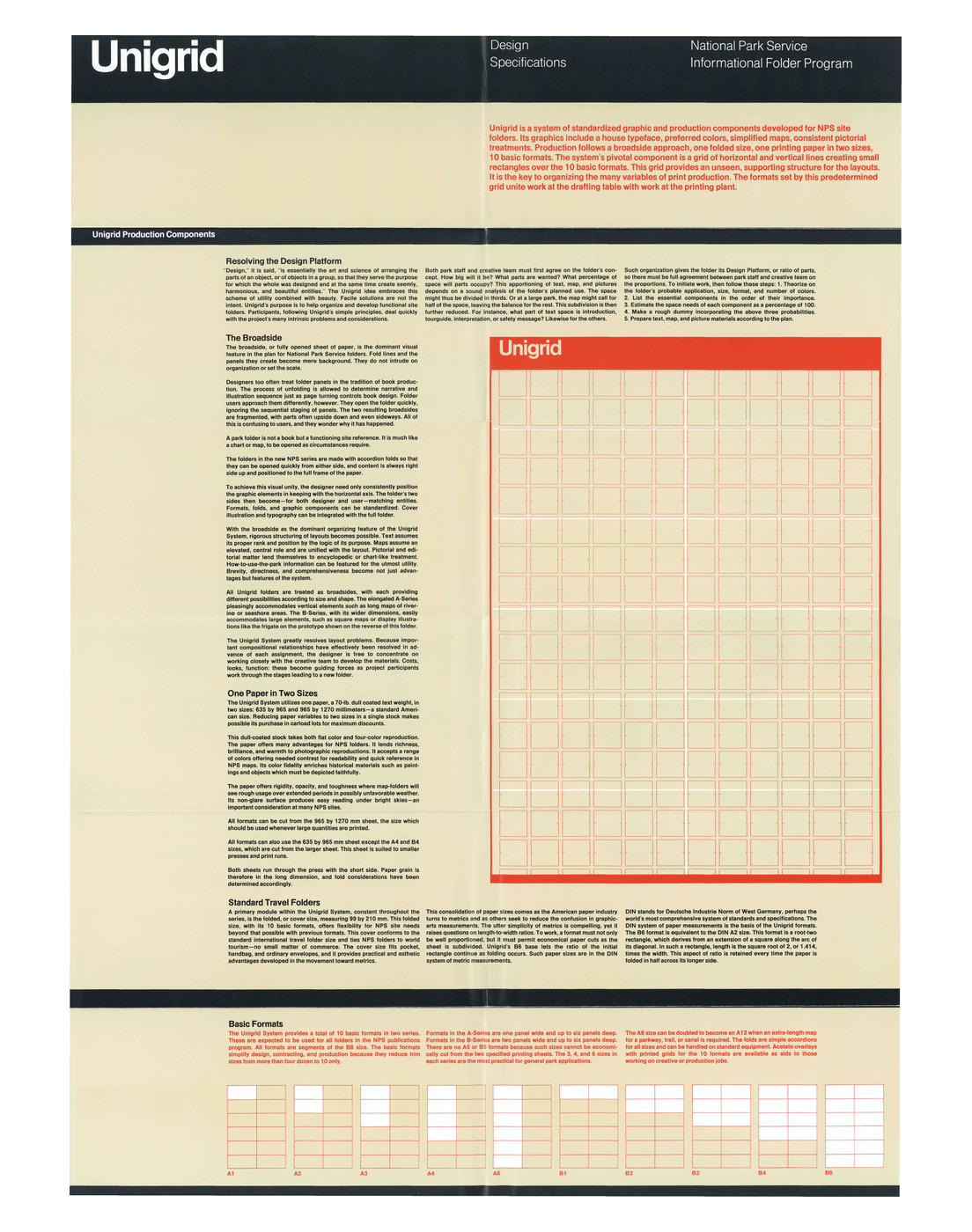
Figure 11Page 2 of the specification, where the grid, paper system, broadside, and format family appear together.
Page 2 of the National Park Service Unigrid Design Specifications, headed Unigrid Production Components: the design platform and broadside texts at the left, the red B6 grid drawing at the right, and the ten basic formats A1 to A6 and B1 to B6 ruled across the foot of the sheet.

Reconstructing B6

B6 is the largest base format in the system and the principal geometric case reconstructed here. It is especially useful because so many relationships can be read together on one sheet: trim, modules, intervals, title region and bars, fold structure, and the visible phase of the grid.

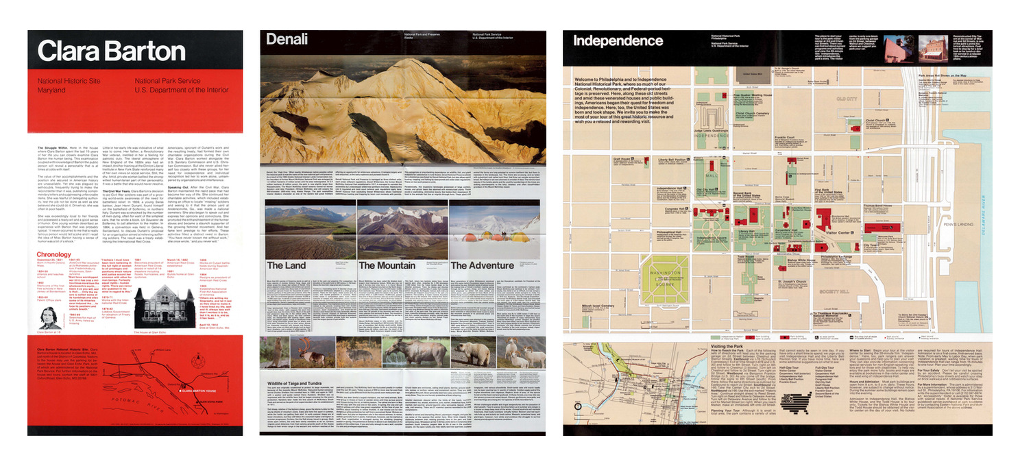
Figure 12Three Unigrid publications showing variation within the same system.
Three Unigrid folders placed side by side at a common height: Clara Barton National Historic Site, 1978, a narrow sheet of text columns with a red chronology band; Denali National Park and Preserve, 1984, a wide sheet led by a full-width photographic panorama; and Independence National Historical Park, 1989, a sheet given almost entirely to a city map. Each carries the same black title band across its head.

Established geometry

RelationshipValueEvidence class
B6 trim420 × 594 mmSpecified
Folded panel99 × 210 mmSpecified
B-module7 picas × 80 ptSpecified
B-module expressed in points84 × 80 ptDerived
Column interval1 pica = 12 ptSpecified / derived conversion
Row interval10 ptSpecified
Horizontal pitch96 ptDerived
Vertical pitch90 ptDerived
Title bar100 ptSpecified
Title type below top trim10 ptSpecified
Bottom and divisional bars25 ptSpecified
Fully exposed field12 columns × 17 rowsSpecified graphically
Fully exposed module count204Derived
Fully exposed field1,140 × 1,520 ptDerived
Complete row within title region1 rowDerived reconstruction
Complete rows through title and exposed field18Derived reconstruction
Next lattice rowbegins before lower trim; clippedDerived reconstruction

The module, intervals, title bar, and bar thicknesses come from the specification’s measurement and title sections.1921 The twelve-by-seventeen exposed matrix is counted from the published drawing and corroborated by UniDescription.7 Arithmetic is kept separate from those observations.

The exposed field

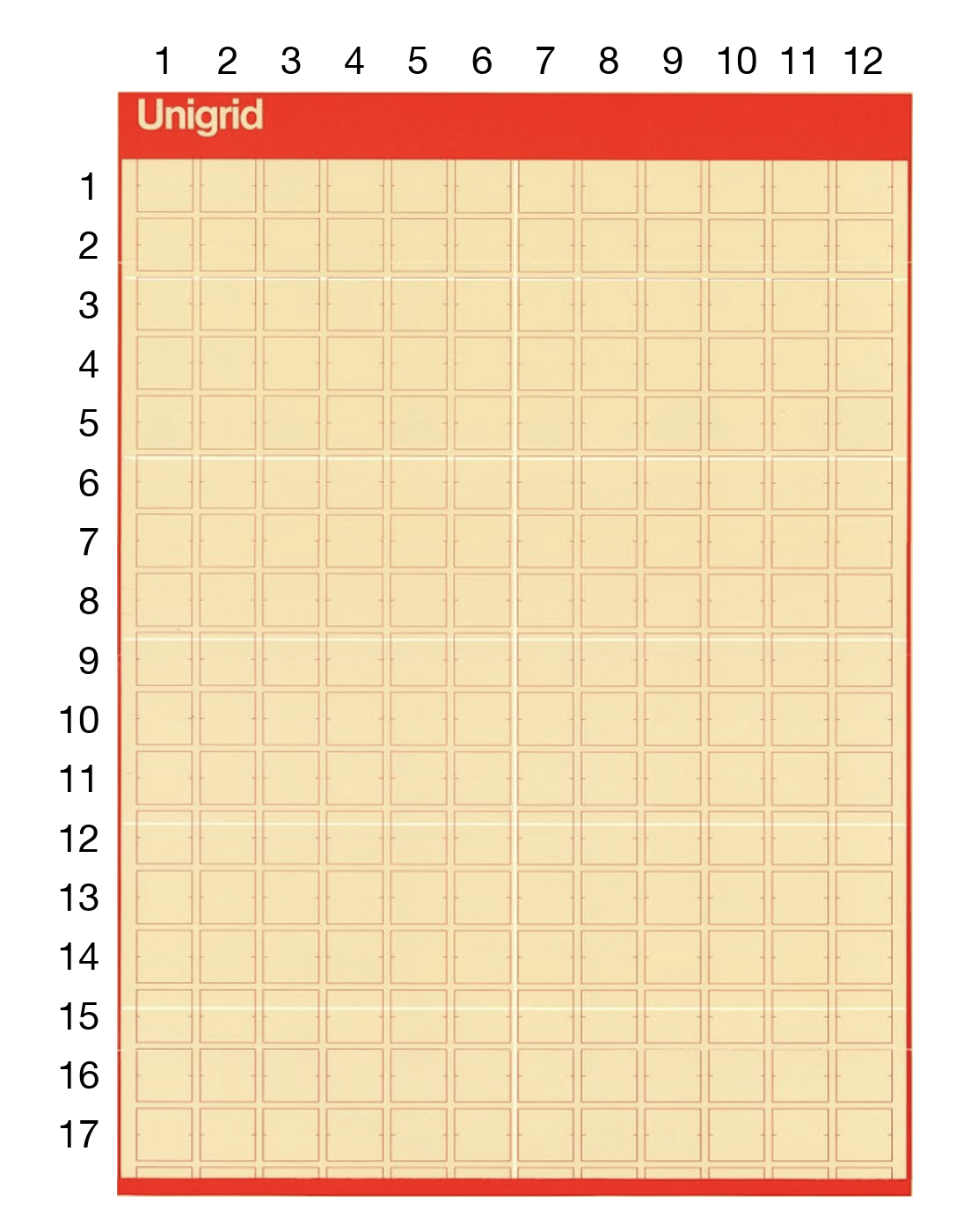
The B6 illustration contains twelve complete module columns and seventeen complete module rows fully exposed beneath the title region. The count is directly visible in the historical drawing. UniDescription independently describes the same illustration as boxes “stacked 12 wide and 17 deep.”7

The exposed field contains 204 complete modules:

12×17=20412\times17=204

Its dimensions in the grid’s native point system are:

Wf=12(84)+11(12)=1,140 ptW_f=12(84)+11(12)=1{,}140\text{ pt}
Wf=12(84)+11(12)=1,140 pt\begin{aligned} W_f &= 12(84)+11(12) \\ &= 1{,}140\text{ pt} \end{aligned}
Hf=17(80)+16(10)=1,520 pt.H_f=17(80)+16(10)=1{,}520\text{ pt}.
Hf=17(80)+16(10)=1,520 pt\begin{aligned} H_f &= 17(80)+16(10) \\ &= 1{,}520\text{ pt} \end{aligned}

The point dimensions are the result that matters here. Converting them to millimetres requires a point convention that the historical specification does not state. The document itself mixes millimetres for trim, picas for horizontal grid measurements, and points for vertical grid measurements without giving a conversion rule between those systems.19

For comparison, a 72-point-per-inch PostScript convention gives approximately 402.17 × 536.22 mm for the exposed field; a 72.27-point-per-inch traditional convention gives approximately 400.66 × 534.22 mm.26 These converted values are contemporary comparisons, not additional historical measurements.

Figure 13aUnaltered B6 grid drawing from the 1985 specification.
The B6 grid drawing from page 2 of the 1985 specification, unaltered: the red title bar reading Unigrid above a lattice of small rectangles twelve columns wide, each module drawn with its own corner ticks, the seventeen fully exposed rows running down to a red bar at the foot of the frame.
Figure 13bThe same source annotated with columns 1–12 and the seventeen complete rows fully exposed beneath the title region.
The same unaltered B6 grid drawing set into white margins and annotated in black: the numerals 1 to 12 above the twelve module columns, and the numerals 1 to 17 down the left side against the seventeen module rows fully exposed beneath the red title bar, with the eighteenth row visibly cut by the frame below row 17.

Vertical phase and the title-region row

The B-module is 80 points high and the interval between rows is 10 points. The vertical pitch is therefore:

py=80+10=90 pt.p_y=80+10=90\text{ pt}.

In the source drawing, the first fully exposed row begins at the lower edge of the 100-point title region. Extending the established 90-point cadence upward by one pitch gives:

100−90=10 pt.100-90=10\text{ pt}.

The preceding module occupies:

10 pt≤Y≤90 pt,10\text{ pt}\leq Y\leq90\text{ pt},

followed by the normal interval:

90 pt≤Y≤100 pt.90\text{ pt}\leq Y\leq100\text{ pt}.

The title region therefore accommodates the sequence:

10+80+10=100 pt.10+80+10=100\text{ pt}.

One complete 80-point module row lies within the title region, with 10 points above it and the normal 10-point row interval below it. The source does not state this in prose. The result follows from the specified title height, specified module and interval dimensions, and the phase of the grid shown in the drawing, so it remains a derived reconstruction.

Including that row, the lattice from its first module start through the end of the seventeenth exposed row contains eighteen complete module rows:

18(80)+17(10)=1,610 pt.18(80)+17(10)=1{,}610\text{ pt}.

Across twelve columns, those eighteen complete row positions contain:

12×18=21612\times18=216

module positions. The number 216 describes a reconstructed extent of the lattice. The graphically exposed field remains 204 modules.

Lower-edge sensitivity

The established cadence begins another row before the lower trim. The exact amount of that row retained by the sheet depends on the point convention used to compare it with the 594 mm trim.

With sheet coordinates beginning at the upper trim, the eighteenth complete row ends at:

Y=1,620 pt,Y=1{,}620\text{ pt},

the following interval ends at:

Y=1,630 pt,Y=1{,}630\text{ pt},

and the next 80-point module begins there. A complete module would end at:

Y=1,710 pt.Y=1{,}710\text{ pt}.

Two conventional point systems give different numerical trim positions.26

Conversion conventionPoints per inch594 mm expressed in pointsRow retained before trimRow beyond trim
PostScript721,683.8 pt53.8 pt26.2 pt
Traditional72.271,690.1 pt60.1 pt19.9 pt

Both conventions lead to the same geometric conclusion: the cadence reaches the start of another row at 1,630 points, and the 594 mm sheet cannot contain that 80-point row in full.

The specified lower bar is 25 points high.21 If its lower edge is registered to the lower trim as depicted, the amount of the projected row visible above the bar is approximately 28.8 points under the PostScript convention and 35.1 points under the traditional convention. That partition remains conditional on both the point convention and the depicted registration of the bar.

Together, Figures 13a–13c form the evidence plate for the reconstruction: source drawing, annotated count, reconstructed lattice.

Figure 13cReconstructed B6 vertical lattice. The plate shows the 420 × 594 mm trim, 100-point title region, 90-point pitch, complete title-region row, seventeen fully exposed rows, the following interval, projected clipped row, 25-point lower bar, and lower trim.
The B6 sheet reconstructed as a plate in black on white: the title region across the head with the word Unigrid, twelve columns of modules at the specified pitch, seventeen rows fully exposed, the following row begun and cut by the lower bar, and hairline rules down both sides of the trim.

Panels and modules

B6 carries twelve physical folded panels on each side: two across and six deep.16 Panels and modules describe different structures. The panels determine the physical fold pattern of the broadside. The twelve-column module field determines graphic position and span. Their shared number on one axis does not make them interchangeable.

Coordinate model

To keep sheet registration separate from local field addressing, the reconstruction uses two coordinate systems.

Sheet-space lattice. Sheet coordinates begin at the upper-left trim corner. The vertical lattice is registered from the phase established above:

Yr=10+90r,Y_r=10+90r,

where rr is a zero-based sheet-space lattice row index. The module occupies:

[Yr,  Yr+80].[Y_r,\;Y_r+80].

Under the reconstruction:

r=0r=0

is the complete row within the title region;

r=1,…,17r=1,\ldots,17

are the seventeen complete rows fully exposed beneath it; and

r=18r=18

begins at 1,630 points and is clipped by the lower trim.

Local exposed-field coordinates. Within the twelve-by-seventeen exposed field, let ii denote the zero-based column and jj the zero-based row:

i∈{0,…,11},j∈{0,…,16}.i\in\{0,\ldots,11\},\qquad j\in\{0,\ldots,16\}.
i∈{0,…,11}j∈{0,…,16}\begin{aligned} i &\in \{0,\ldots,11\} \\ j &\in \{0,\ldots,16\} \end{aligned}

The corresponding sheet-space row is:

r=j+1.r=j+1.

An exposed-field element is:

E=(i,j,w,h),E=(i,j,w,h),

where ww and hh are positive integer spans. Its dimensions are:

WE=84w+12(w−1)W_E=84w+12(w-1)
HE=80h+10(h−1).H_E=80h+10(h-1).

Valid local placements satisfy:

0≤i<12,0≤j<170\leq i<12,\qquad 0\leq j<17
1≤w≤12−i,1≤h≤17−j.1\leq w\leq12-i,\qquad 1\leq h\leq17-j.
1≤w≤12−i1≤h≤17−j\begin{aligned} 1 &\leq w\leq12-i \\ 1 &\leq h\leq17-j \end{aligned}

The reconstruction establishes horizontal module dimensions and relative positions within the twelve-column field. It does not establish an absolute horizontal field origin against the left trim. Horizontal coordinates are therefore local to the field unless further evidence establishes an X0X_0. Vertical sheet registration is reconstructed separately from the visible phase of the historical drawing.

Keeping the coordinate systems separate avoids treating the residual at the sheet edge as evidence of symmetrical historical margins.

From geometry to rule

The arithmetic turns evidence into explicit relationships. Modules and intervals become dimensions; positions and spans become integer coordinates and counts. Trim, title and divisional bars, folds, and the module field remain separate parts of the geometry.

The model then supports three operations:

  1. Generation. The rules generate new rectangles.
  2. Validation. The model rejects rectangles whose coordinates or spans exceed the declared field.
  3. Transformation with provenance. A relationship can be implemented in another medium with its historical source and contemporary treatment recorded separately.

From reconstruction to computation

Transferable relationships

The software implements five selected relationships from the reconstruction:

fixed module dimensions; fixed intervals; integer coordinates and spans; a shared lattice; material capacity.

The unit can change while these relationships remain explicit. A typographic point, millimetre, and CSS pixel have different physical meanings. What transfers is the structure of the geometry: fixed dimensions, integer coordinates and spans, shared edges, and the number of complete modules the available material can contain.

A shared lattice can be stated formally. Let:

px=mx+gx,py=my+gyp_x=m_x+g_x,\qquad p_y=m_y+g_y
px=mx+gxpy=my+gy\begin{aligned} p_x &= m_x+g_x \\ p_y &= m_y+g_y \end{aligned}

be the horizontal and vertical pitches. For a field origin (X0,Y0)(X_0,Y_0), module start and end edges are:

Xi−=X0+ipx,Xi+=Xi−+mxX_i^-=X_0+i p_x,\qquad X_i^+=X_i^-+m_x
Xi−=X0+ipxXi+=Xi−+mx\begin{aligned} X_i^- &= X_0+i p_x \\ X_i^+ &= X_i^-+m_x \end{aligned}
Yj−=Y0+jpy,Yj+=Yj−+my.Y_j^-=Y_0+j p_y,\qquad Y_j^+=Y_j^-+m_y.
Yj−=Y0+jpyYj+=Yj−+my\begin{aligned} Y_j^- &= Y_0+j p_y \\ Y_j^+ &= Y_j^-+m_y \end{aligned}

A cell with integer coordinates (i,j)(i,j) and integer spans (w,h)(w,h) occupies:

[Xi−,Xi+w−1+]×[Yj−,Yj+h−1+].[X_i^-,X_{i+w-1}^+]\times[Y_j^-,Y_{j+h-1}^+].

Independently authored components therefore begin and end on edges generated by the same module-and-interval construction. Shared lattice names that common coordinate discipline.

Fixed size across historical formats

The historical specification states that type, maps, and illustrations keep their size as the publication format changes. Smaller formats carry a different amount of material rather than proportionally scaled versions of the same graphic components.27

The digital implementation keeps the constituent geometry fixed while available space determines how much fits.

No format in the Unigrid System requires any alteration in size of type, maps, or illustrations. Small formats are not miniatures of larger formats.

National Park Service, Unigrid Design Specifications, 1985

Material capacity

Let:

mx=module widthm_x=\text{module width}
gx=horizontal interval.g_x=\text{horizontal interval}.

For available width WW, the number of complete modules that physically fit is:

C(W)=⌊W+gxmx+gx⌋.C(W)=\left\lfloor\frac{W+g_x}{m_x+g_x}\right\rfloor.

A field of NN complete columns occupies:

F(N)=Nmx+(N−1)gx.F(N)=Nm_x+(N-1)g_x.

The residual width is:

R(W,N)=W−F(N).R(W,N)=W-F(N).

When that field is centred:

Rstart=Rend=R(W,N)2.R_{start}=R_{end}=\frac{R(W,N)}{2}.

The equations require no device categories. Width changes alter the number of complete modules the material can contain while module dimensions and intervals remain fixed.

Figure 14One Unigrid composition at multiple material capacities.
One authored Unigrid composition rendered by the package at three material capacities, twelve, nine and six modules. The four cells keep their exact coordinates and the modules keep their exact size in all three; only the field around them changes, leaving fewer empty modules to the right as it narrows.

Authored composition

An authored composition declares a finite horizontal coordinate field of AA columns. Cells may carry:

x,  y,  w,  hx,\;y,\;w,\;h

for integer position and span. The active column count is:

N(W)=min⁡(A,max⁡(1,C(W))).N(W)=\min\left(A,\max(1,C(W))\right).
N(W)=min⁡(A,max⁡(1,C(W)))\begin{aligned} N(W) &= \min\big(A, \\ &\qquad \max(1,C(W))\big) \end{aligned}

At full authored capacity, explicit coordinates can be honoured as one two-dimensional arrangement. Below that capacity, the implementation releases explicit positions together and continues in source order unless another authored behaviour has been declared. Releasing them together prevents collisions and unintended reading order.

The authored ceiling and coordinate-release behaviour are adapted implementation rules.

Fluid composition

A fluid composition declares no authored horizontal coordinate field. Cells carry span and source order, and the field uses complete modules permitted by available width:

Nfluid(W)=max⁡(1,C(W)).N_{\mathrm{fluid}}(W)=\max(1,C(W)).

There is no coordinate threshold to release. Authored and fluid composition use the same module geometry with different placement rules.

Coordinates and spans remain whole

A cell spanning ww columns occupies:

WE=wmx+(w−1)gx.W_E=w m_x+(w-1)g_x.

A cell spanning hh rows occupies:

HE=hmy+(h−1)gy.H_E=h m_y+(h-1)g_y.

Position and span are integer relationships. Responsive behaviour does not multiply them by a viewport ratio. If a cell is wider than the active field, the implementation may expose overflow, release its authored position, or apply another explicit rule. Shrinking the module or proportionally remapping its span would alter the declared geometry.

What changes on screen

Paper is finite in both axes. A B6 sheet has a fixed physical width and height. A browser field has variable inline width while the document can continue in the block direction. Runtime measurement, source order, scrolling, reflow, overflow, and continuing rows become part of the material condition.

Those are properties of the browser implementation, so this paper classifies them as adapted.

Paper resolves these five relationships against a bounded sheet. Screen resolves them against available width and continuing document height.

Numerical values are implementation parameters

The historical B-module measures 84 × 80 points with 12 × 10 point intervals. Those numbers belong to the print specification.19

The KhannaOffice web implementation uses the same numerical parameters in a different unit system: 84 × 80 CSS-pixel modules with 12 × 10 pixel intervals.28 These are adapted implementation parameters. The shared numerical values are deliberate. Typographic points and CSS pixels retain different physical meanings.

A twelve-column digital field therefore occupies:

12(84)+11(12)=1,140 px.12(84)+11(12)=1{,}140\text{ px}.

The implementation preserves the numerical module and interval relationships while available width determines how many complete modules fit.

The implementation also distinguishes a finite authored model from a fluid model with no authored coordinate ceiling. Twelve columns describe the historical B6 field and can also describe a particular authored digital composition; they do not impose a universal ceiling on screen layout.

The field widths therefore correspond numerically: 1,140 pt historically / 1,140 px digitally. The units retain their separate physical meanings.

Executable Unigrid

Representation

A software implementation can represent the transferable geometry with four primary parameters:

module width  = m_x
module height = m_y
column gap    = g_x
row gap       = g_y

A cell is represented as:

E = (x, y, w, h)

for authored compositions, or by span and source order for fluid compositions.

The representation is intentionally small. It only needs to hold the relationships that determine position, span, alignment, and capacity.

Validation

For a finite field of nxn_x columns and nyn_y rows, an authored element is valid when:

0≤x<nx0\leq x<n_x
0≤y<ny0\leq y<n_y
1≤w≤nx−x1\leq w\leq n_x-x
1≤h≤ny−y.1\leq h\leq n_y-y.

An implementation can add further rules for overlap, duplicate identifiers, incomplete coordinates, or source-order requirements.

The specification's dimensions define which states are valid.

React component model

The public package is @khannaoffice/unigrid. The software record cited in this paper is release 1.0.0 at commit 931c228ccaf7eff72b7af0f565bc5e88d5b8810f.28 A composition can be written directly in modules:

import {
  Unigrid,
  Cell,
} from "@khannaoffice/unigrid";

<Unigrid authoredColumns={6} initialColumns={6}>
  <Cell x={0} y={0} w={4} h={2}>
    Body
  </Cell>

  <Cell x={4} y={0} w={2} h={1}>
    Record
  </Cell>
</Unigrid>

Unigrid establishes the field and its geometry. Cell expresses position and span.

The package also exposes pure geometry, placement, validation, capacity, and audit functions. These functions let the geometry be inspected independently of React rendering.

Verification

Historical reconstruction and software implementation require different forms of verification. A software test can establish implementation behaviour; it cannot establish a historical premise that the code was given. A source drawing can establish historical evidence; it cannot establish that a browser package obeys its own declared rules.

Historical verification

Specified values are read from the 1985 specification. Graphically specified relationships are counted from the source drawing. Derived values are recalculated from identified inputs. Inferred relationships remain labelled as inference.

The B6 reconstruction is presented as a single sequence of evidence:

  1. the untouched historical drawing;
  2. the annotated twelve-column by seventeen-row exposed count;
  3. the derived 1,140 × 1,520 point exposed field;
  4. the 90-point cadence extended through the title region;
  5. the lower-edge sensitivity analysis.

Figures 13a–13c present the source drawing, counted field, and reconstructed lattice used by the calculations.

Software verification

The software evidence cited here comes from release 1.0.0 at a fixed commit.

Release @khannaoffice/unigrid 1.0.0 is identified by commit:

931c228ccaf7eff72b7af0f565bc5e88d5b8810f

The checked-in deterministic report verification/local-verification.json was generated on 12 August 2026 at 03:12:30 UTC on Node v26.3.1. It records allChecksPassed: true, a valid twelve-state material audit, and capacities from one through twelve columns. Every state reports 84 × 80 pixel modules with 12 × 10 pixel intervals; the twelve-column state resolves to 1,140 pixels.29

Separate checked-in Playwright reports cover React 18.3.1 and React 19.2.6 across Chromium, Firefox, and WebKit. Each report records 123 expected checks, zero skipped, zero unexpected, and zero flaky.30 Those results apply to the release files and runtime versions named in the reports.

Release 1.0.0 predates the corrected B6 row registration. Its reports verify the published screen geometry and browser behaviour, not the revised historical reconstruction.

Provenance across the medium change

When a system moves between media, contemporary adaptations can be mistaken for historical features. The evidence classes keep that boundary explicit.

RelationshipHistorical statusComputational treatment
B-module dimensionsSpecifiedHistorical parameter in B6 reconstruction; numerical basis for adapted CSS default
B-module intervalsSpecifiedHistorical parameter in B6 reconstruction; numerical basis for adapted CSS default
Exposed B6 matrixSpecified graphicallyHistorical field record
Title-region rowDerived reconstructionRepresentable as lattice phase
Lower clipped rowDerived reconstructionRepresentable as trim clipping
Fixed module geometry on screenAdaptedEnforced by software
Material-capacity functionAdaptedComputed from available width
Authored coordinate releaseAdaptedResponsive behaviour
Fluid compositionAdaptedSeparate composition model
CSS-pixel unitsAdaptedDigital implementation parameter
Continuing block-axis rowsAdaptedBrowser material condition

The historical designers did not specify CSS pixels, React, source-order reflow, runtime measurement, or browser overflow. KhannaOffice can use those mechanisms because each is recorded as an adaptation.

The provenance record identifies which relationships come from the historical source, which are derived, and which are introduced by the software.

Limits

Historical scope

Unigrid is larger than the B6 geometry reconstructed here.

The historical system also includes editorial practice, cartography, pictorial commissioning, colour, print procurement, maintenance, fold planning, and decades of institutional development. The executable model concentrates on modular and material relationships.

The 1985 specification is one documented state of a long-running program. Later National Park Service practice changed typography, imagery, maps, and production while retaining a recognizable family structure.2

Attribution

Institutional leadership, consulting design, staff design, later maintenance, historical reconstruction, and software implementation remain separate forms of authorship.

National Park Service sources establish Gleason’s initiating institutional role and Vignelli’s involvement. The 1985 specification identifies Vignelli as consulting designer. His oral history describes both his own contribution and the work of Park Service designers using the system. The Vignelli Center records the names of the wider design team.

KhannaOffice’s reconstruction and software are later work and do not settle unresolved facts in the original record.

Geometric scope

The twelve-column by seventeen-row exposed field is graphically established. The title-region row is a derived reconstruction from specified dimensions and visible phase. The lower continuation is also derived: both point conventions tested here place its start before the lower trim, while its exact division at the bottom bar depends on the convention and the depicted registration of that bar.

Absolute horizontal registration remains unresolved. The source establishes the module dimensions and relative twelve-column field, but not an X0X_0 against trim from which symmetrical margins could be inferred.

Digital scope

The web implementation adds CSS units, authored and fluid composition, material-capacity rules, source-order behaviour, scrolling, overflow, runtime measurement, and continuing document height. These are contemporary adaptations.

Conclusion

Unigrid coordinates graphic form, editorial structure, and print production through repeatable relationships. Format defines the physical sheet; the grid organizes position and span; typography, maps, images, paper, folds, and press conditions operate within the same publication system.

B6 makes part of that structure measurable. The 1985 drawing exposes twelve complete columns by seventeen complete rows built from 84 × 80 point modules and 12 × 10 point intervals. Those values yield a 1,140 × 1,520 point exposed field. The specified 90-point vertical cadence, read against the 100-point title region, supports one further complete row within the title region. The cadence then begins another row before the lower trim. Both conventions place the start of another row before the trim, and under neither convention can the sheet contain it in full.

Formalization turns those observations into rules. Fixed module dimensions, fixed intervals, integer coordinates and spans, a shared lattice, and material capacity can be expressed mathematically and enforced computationally. The browser implements those relationships through documented adaptations.

A surviving brochure preserves one state of Unigrid. The specification preserves part of its grammar. Reconstruction makes that grammar explicit, and computation lets selected rules govern again. That separation allows the reconstructed relationships to be used in another medium without presenting contemporary decisions as historical facts.

Notes

  1. National Park Service, Division of Publications. Unigrid Design Specifications: National Park Service Informational Folder Program. National Park Service, Washington, DC, 1985. Reprint. Recto, introductory text. Digital facsimile hosted by NPSHistory.com. https://npshistory.com/brochures/unigrid.pdf. Primary source.
  2. National Park Service, Harpers Ferry Center. A Brief History of the Unigrid. National Park Service, 2023. Updated March 10, 2023. https://www.nps.gov/subjects/hfc/a-brief-history-of-the-unigrid.htm. Web.
  3. Vincent Gleason. My Idea HFC. National Park Service, 1964. Proposal dated April 20, 1964. https://home.nps.gov/articles/000/my-idea-hfc.htm. Archival document.
  4. Massimo Vignelli. Oral history interview by Mija Riedel, June 6–7, 2011. Archives of American Art, Smithsonian Institution, 2011. https://www.aaa.si.edu/download_pdf_transcript/ajax?record_id=edanmdm-AAADCD_oh_302171. Oral history.
  5. Vignelli Center for Design Studies. National Park Service publication records in the Massimo and Lella Vignelli papers. Including the design-team record reproduced with “Independence”; object records for “Independence” (artsandculture.google.com/asset/independence/PQGJgZgwnAG4yQ), “Crater Lake” (artsandculture.google.com/asset/crater-lake-vignelli-massimo/-AE6TiwEmnAx1Q) and “Denali” (artsandculture.google.com/asset/denali-vignelli-massimo/AgG079SzD1eX3g). https://artsandculture.google.com/asset/independence/PQGJgZgwnAG4yQ. Archive.
  6. Philip B. Meggs; Alston W. Purvis. Meggs’ History of Graphic Design. John Wiley & Sons, Hoboken, NJ, 2011. 5th ed., p. 426. Book.
  7. UniDescription Project. Accessible description of the National Park Service Unigrid specification. Including the B6 grid illustration described as boxes “stacked 12 wide and 17 deep”. https://unidescription.org/account/project/export/270. Web.
  8. Herbert A. Simon. The Sciences of the Artificial. MIT Press, Cambridge, MA, 1996. 3rd ed. Book.
  9. George Stiny; James Gips. Shape Grammars and the Generative Specification of Painting and Sculpture. North-Holland, Amsterdam, 1972. In Information Processing 71, ed. C. V. Freiman, pp. 1460–1465. Book chapter.
  10. The London Charter for the Computer-based Visualisation of Cultural Heritage. 2009. Version 2.1, Principle 3, “Research Sources”. https://londoncharter.org/principles/research-sources.html. Standard.
  11. The London Charter for the Computer-based Visualisation of Cultural Heritage. 2009. Version 2.1, Principle 4, “Documentation,” especially 4.4–4.10. https://londoncharter.org/principles/documentation.html. Standard.
  12. Hugh Denard. A New Introduction to the London Charter. Ashgate, Farnham, 2012. In Paradata and Transparency in Virtual Heritage, ed. Anna Bentkowska-Kafel, Drew Baker, and Hugh Denard, 57-71. https://londoncharter.org/introduction.html. Book chapter.
  13. Stephen Grace; Gareth Knight; Lynne Montague. Investigating the Significant Properties of Electronic Content over Time: Final Report. JISC, The National Archives, and King’s College London, 2009. Version 1.0. https://significantproperties.kdl.kcl.ac.uk/. Report.
  14. Christoph Becker. Metaphors We Work By: Reframing Digital Objects, Significant Properties, and the Design of Digital Preservation Systems. Archivaria 85, 2018. pp. 6–36. https://archivaria.ca/index.php/archivaria/article/view/13628. Journal article.
  15. Roberto Di Cosmo; Stefano Zacchiroli. Software Heritage: Why and How to Preserve Software Source Code. Proceedings of iPRES 2017: 14th International Conference on Digital Preservation, Kyoto, 2017. https://www.softwareheritage.org/wp-content/uploads/2020/01/ipres-2017-swh.pdf. Conference paper.
  16. National Park Service, Division of Publications. Unigrid Design Specifications. 1985. Verso, “Basic Formats” and “Standard Travel Folders”. Primary source.
  17. National Park Service, Division of Publications. Unigrid Design Specifications. 1985. Verso, “The Broadside”. Primary source.
  18. National Park Service, Division of Publications. Unigrid Design Specifications. 1985. Recto, “The Grid Behind the Layout”. Primary source.
  19. National Park Service, Division of Publications. Unigrid Design Specifications. 1985. Recto, “Measurements”. Primary source.
  20. National Park Service, Division of Publications. Unigrid Design Specifications. 1985. Recto, “House Typeface,” “Titles,” “Texts,” and “Display Type and Captions”. Primary source.
  21. National Park Service, Division of Publications. Unigrid Design Specifications. 1985. Recto, “Titles” and “Bars and Dividers”. Primary source.
  22. National Park Service, Division of Publications. Unigrid Design Specifications. 1985. Recto, “Preferred Colors”. Primary source.
  23. National Park Service, Division of Publications. Unigrid Design Specifications. 1985. Recto, “Maps” and “Pictorial Features”. Primary source.
  24. National Park Service, Division of Publications. Unigrid Design Specifications. 1985. Verso, “One Paper in Two Sizes” and “Standard Travel Folders”. Primary source.
  25. National Park Service, Division of Publications. Unigrid Design Specifications. 1985. Verso, “Resolving the Design Platform”. Primary source.
  26. Adobe. Format characters in Photoshop: Define the point size unit. Adobe documents two contemporary point/pica conventions: PostScript at 72 points per inch and Traditional at 72.27 points per inch. This source is used only to state the conventions tested in the sensitivity analysis; it does not establish which convention the National Park Service used in the historical specification. https://helpx.adobe.com/ca/photoshop/using/formatting-characters.html. Technical documentation.
  27. National Park Service, Division of Publications. Unigrid Design Specifications. 1985. Recto, “Size and Scale”. Primary source.
  28. KhannaOffice. @khannaoffice/unigrid 1.0.0. 2026. Release commit 931c228ccaf7eff72b7af0f565bc5e88d5b8810f, August 12, 2026. https://github.com/rohanarickhanna/unigrid/commit/931c228ccaf7eff72b7af0f565bc5e88d5b8810f. Software.
  29. KhannaOffice. verification/local-verification.json. 2026. Package 1.0.0, generated August 12, 2026, 03:12:30 UTC, release commit 931c228ccaf7eff72b7af0f565bc5e88d5b8810f. https://github.com/rohanarickhanna/unigrid/blob/931c228ccaf7eff72b7af0f565bc5e88d5b8810f/verification/local-verification.json. Verification record.
  30. KhannaOffice. verification/playwright-react-18.3.1.json and verification/playwright-react-19.2.6.json. 2026. Package 1.0.0, release commit 931c228ccaf7eff72b7af0f565bc5e88d5b8810f. https://github.com/rohanarickhanna/unigrid/tree/931c228ccaf7eff72b7af0f565bc5e88d5b8810f/verification. Verification record.

References

Primary and institutional sources

  • National Park Service, Division of Publications. Unigrid Design Specifications: National Park Service Informational Folder Program. Reprint. Washington, DC: National Park Service, 1985. Digital facsimile hosted by NPSHistory.com. npshistory.com/brochures/unigrid.pdf
  • National Park Service, Harpers Ferry Center. “A Brief History of the Unigrid.” Updated March 10, 2023. nps.gov/subjects/hfc/a-brief-history-of-the-unigrid.htm
  • Gleason, Vincent. “My Idea HFC.” Proposal, April 20, 1964. National Park Service. home.nps.gov/articles/000/my-idea-hfc.htm
  • Vignelli, Massimo. Oral history interview by Mija Riedel, June 6–7, 2011. Archives of American Art, Smithsonian Institution. aaa.si.edu
  • Vignelli Center for Design Studies. National Park Service publication records in the Massimo and Lella Vignelli papers. artsandculture.google.com
  • UniDescription Project. Accessible description of the National Park Service Unigrid specification. unidescription.org

Secondary and methodological literature

  • Becker, Christoph. “Metaphors We Work By: Reframing Digital Objects, Significant Properties, and the Design of Digital Preservation Systems.” Archivaria 85 (2018): 6–36. archivaria.ca
  • Denard, Hugh. “A New Introduction to the London Charter.” In Paradata and Transparency in Virtual Heritage, edited by Anna Bentkowska-Kafel, Drew Baker, and Hugh Denard, 57–71. Farnham: Ashgate, 2012. londoncharter.org
  • Di Cosmo, Roberto, and Stefano Zacchiroli. “Software Heritage: Why and How to Preserve Software Source Code.” In Proceedings of iPRES 2017: 14th International Conference on Digital Preservation. Kyoto, 2017. softwareheritage.org
  • Grace, Stephen, Gareth Knight, and Lynne Montague. Investigating the Significant Properties of Electronic Content over Time: Final Report. Version 1.0. JISC, The National Archives, and King’s College London, 2009. significantproperties.kdl.kcl.ac.uk
  • The London Charter for the Computer-based Visualisation of Cultural Heritage. Version 2.1. 2009. londoncharter.org/principles.html
  • Meggs, Philip B., and Alston W. Purvis. Meggs’ History of Graphic Design. 5th ed. Hoboken, NJ: John Wiley & Sons, 2011. See p. 426 for the Unigrid attribution.
  • Simon, Herbert A. The Sciences of the Artificial. 3rd ed. Cambridge, MA: MIT Press, 1996.
  • Stiny, George, and James Gips. “Shape Grammars and the Generative Specification of Painting and Sculpture.” In Information Processing 71, edited by C. V. Freiman, 1460–1465. Amsterdam: North-Holland, 1972.

Technical and computational records

  • Adobe. “Format characters in Photoshop.” “Define the point size unit.” helpx.adobe.com
  • KhannaOffice. @khannaoffice/unigrid 1.0.0. Release commit 931c228ccaf7eff72b7af0f565bc5e88d5b8810f, August 12, 2026. github.com
  • KhannaOffice. verification/local-verification.json. Package 1.0.0. Generated August 12, 2026, 03:12:30 UTC. github.com
  • KhannaOffice. verification/playwright-react-18.3.1.json and verification/playwright-react-19.2.6.json. Package 1.0.0. Generated August 12, 2026. github.com

Citation

Plain text

Khanna, Rohan. "Unigrid: The National Park Service Publication System, Reconstructed." KhannaOffice, 2026. https://khannaoffice.com/research/unigrid/

BibTeX

@techreport{khanna-unigrid-reconstructed,
  author      = {Khanna, Rohan},
  title       = {Unigrid: The National Park Service Publication System, Reconstructed},
  institution = {KhannaOffice},
  year        = {2026},
  version     = {1.0},
  url         = {https://khannaoffice.com/research/unigrid/}
}

Revision history

VersionChange
1.0First publication.

Record

Research ID
R-001
Title
Unigrid: The National Park Service Publication System, Reconstructed
Author
Rohan Khanna
Publisher
KhannaOffice
Version
1.0
Status
Published
Published
Modified
Permanent URL
https://khannaoffice.com/research/unigrid/
Subject
National Park Service Unigrid; Vincent Gleason; Massimo Vignelli; Dennis McLaughlin; publication design; B6 format; modular grids; typography; print production; design systems; computational reconstruction; executable preservation
Software release cited
@khannaoffice/unigrid 1.0.0
Release commit
931c228ccaf7eff72b7af0f565bc5e88d5b8810f
Source repository
rohanarickhanna/unigrid
Primary facsimile checksum
e3c7521dc5b06146de0fdc50cd687f76222710fc7745cbc43c712a6c824a1fa0 — newly acquired September 10, 2026 snapshot; identity with the September 7 consulted bytes is not established.